
Last Update: 2024-05-07
© 2003 - 2024,
GPS/BGT:
GPS Satellite Receiver HF Modular Rack Case
Key Features:
- 2x time trigger inputs
- 2x RS-232 interfaces
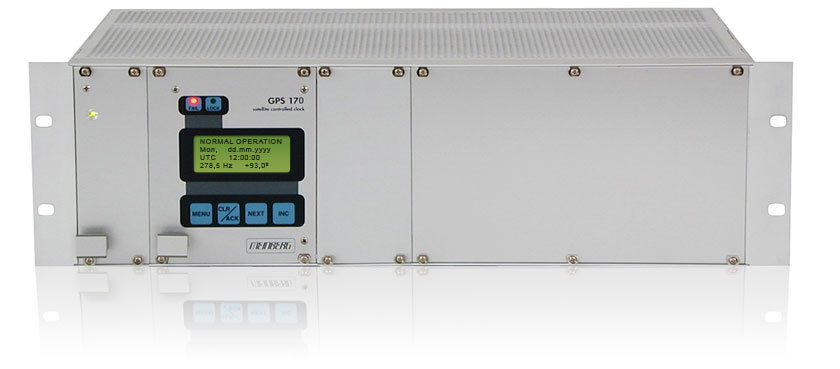
- LC-Display, 4 x 16 characters
- Integrated GPS satellite receiver
- Frequency synthesizer
- Antenna-/converter unit (included)
GPS/BGT is a set of equipment composed of a GPS satellite controlled clock together with a power supply unit, both installed in a metal 19" Modular chassis and ready to operate. The interfaces provided by GPS/BGT are accessible via connectors in the rear panel of the case. The hardware of the GPS receiver is a 100 mm x 160 mm microprocessor board. The 105 mm wide front panel integrates a 4 x 16 character LC display, two LED indicators and 4 push buttons. The receiver is connected to the antenna/converter unit by a 50 ohm coaxial cable. The antenna/converter unit is powered (DC insulation 1000 V DC) via the antenna cable. As an option, an antenna splitter for up to four receivers connected to one antenna is available.
The GPS receiver provides different optional outputs, i.e. three progammable pulse outputs, modulated/unmodulated time code output, and up to a total of four RS232 COM ports. Additionally, you can order the GPS/BGT with different OCXOs (e.g. OCXO-LQ / MQ / HQ / DHQ or an external Rubidium) to match the required accuracy.
Example of Configuration
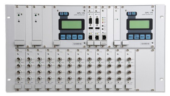
The customized device above is an example for a redundant time server in 6u housing, with 2 x power supply, 2 x LAN CPU, TCG Time Code Generator and a SCU-XPT switch card with an additional network interface.
- LAN CPU: single board computer with a LINUX operating system
- TCG: IRIG or AFNOR time code generator with various outputs
The Board TCV4 has been designed for the distribution of IRIG-A/B time code signals. Four signal outputs are available via front panel BNC connectors, all output connectors can be mounted on the backside of the rack on special request. A green LED, placed in the board's front panel, indicates that the input signal is sufficient for operation.
Due to the input amplifier's adjustable gain TCV4 boards are cascadable.
